Unknown Facts About Wedge Barriers
Getting The Wedge Barriers To Work
Getting The Wedge Barriers To Work
g., spring support 65 )might be fixed to completion of the spring rod 58 to enable compression of the springtimes 60. As the springtimes 60 are compressed between the springtime supports 62, the spring assembly 54 produces a force acting on the camera combined to the springtime rod 58 in a direction 66. For instance, the continuing to be pressure put on
the webcam to release the wedge plate 16 may be offered by an electromechanical actuator 84 or various other actuator. Therefore, the springtime setting up 54 and the actuator 84(e. g., electromechanical actuator)may run together to equate the camera and lift the wedge plate 16.
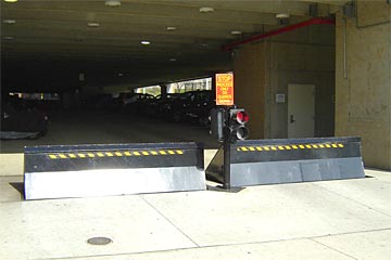
As mentioned above, the springtime setting up 54 puts in a continuous pressure on the camera, while the electromechanical actuator might be controlled to apply a variable force on the web cam, consequently enabling the training and lowering( i. e., releasing and pulling back )of the wedge plate 16. In specific embodiments, the continuous pressure used by the springtime assembly 54 might be flexible. g., electromechanical actuator) is handicapped. As will certainly be valued, the spring setting up 54 may be covered and shielded from debris or other components by a cover plate(e. g., cover plate 68 displayed in FIG. 4) that may be significantly flush with the elevated surface 38 of the foundation 14. As discussed over, in the deployed position, the wedge plate 16 serves to obstruct access or traveling beyond the barrier 10. The barrier 10(e. g., the wedge plate 16 )might obstruct pedestrians or cars from accessing a building or pathway. As discussed above, the obstacle 10 is affixed to the anchor 30 safeguarded within the structure 14,
front brackets 71. As a result, the affiliation assemblies 72 might pivot and rotate to allow the collapse and expansion of the linkage assemblies 72 throughout retraction and deployment of the bather 10. The affiliation assemblies 72 cause motion of the wedge plate 16 to be restricted. If an automobile is taking a trip in the direction of the deployed wedge plate 16(e. For instance, in one circumstance, the security legs 86 might be extended throughoutmaintenance of the barrier 10. When the safety legs 86 are deployed, the security legs 86 support the weight of the wedge plate 16 versus the surface area 12. Because of this, the training device 50 might be shut off, serviced, eliminated, replaced, and so forth. FIG. 5 is partial perspective view of an embodiment of the surface-mounted wedge-style barrier 10, highlighting the web cam 80 and the cam surfaces 82 of the lifting system 50. Especially, two camera surface areas 82, which are described as lower camera surface areas 83, are positioned below the webcam 80. The lower camera surface areas 83 may be taken care of to the surface area 12 (e. As an example, the reduced cam surface areas 83 and try this out the placing plate 85 might create a solitary piece that is secured to the support 30 by screws or other mechanical bolts. Furthermore, two camera surfaces 82, which are described as upper web cam surfaces 87, are positioned above the cam 80 and paired to (e. In various other personifications, intervening layers or plates may be positioned between the surface 12 and the reduced webcam surface areas 83 and/or the wedge plate 16 and the top webcam that site surface areas 87 As stated over, the camera
80 translates along the webcam surfaces 82 when the wedge plate 16 is raised from the retracted position to the deployed position. Additionally, as pointed out above, the spring setting up 54 (see FIG. 3 )may supply a force acting on the camera 80 in the direction 102 using spring pole 58, which may minimize the pressure the electromechanical actuator 84 is needed to put on the web cam 80 in order to actuate and raise the wedge plate 16. 1 )to the released placement(see FIG. 4). As shown, the web cam 80 includes track wheels 104(e. g., rollers), which get in touch with and equate along the cam surface areas 82 throughout operation.